National
Electric Signaling Company
Brant Rock, Massachusetts
Reginald Aubrey Fessenden web page...
Radio
station 'BO'
Bravo Ocean
The Western
Tower: Brant Rock on the Massachusetts sea coast...
Where the
world's first Trans Oceanic Radio Communications took place...
Where the
world's first radio voice was heard across any ocean...
Where the
world's first radio voice broadcast was made...
And MANY radio inventive firsts...
Updated and remove broken links: 2-21-15
Fessenden
on Roanoke
Island by Jack Belrose, VE2CV
Christmas Eve
Revisited by
Jack Belrose, VE2CV
Jack Belrose home
brew alternator and original program repro played over it...
The Eastern
Tower @ Machrihanish Scotland
Duncan MacArthur, GM3TNT and an account of his recollections
Recent Boston
Globe article
An Excellent biography of Reg
Fessenden by Dr. Frederick Seitz in the
Transactions of the American Philosophical Society
Download a great Fessenden write up by Jack Belrose, VE2CV... Belrose.pdf
Dr. Belrose discussion on early antenna measurements and
performance... Belrose2.pdf
Reginald Fessenden's Deluged
Civilization Chapters 1-6 published in 1923...
Deluged Civilization Chapter 7-10 published in 1933...
Deluged Civilization Chapter 11 published in 1927...
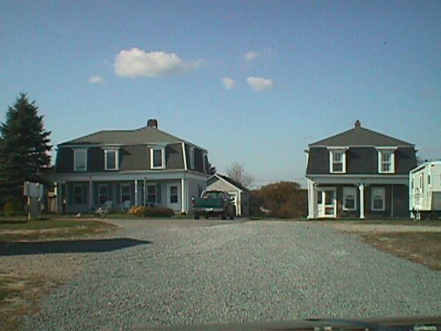
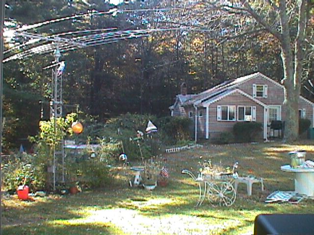
Little is left today of the National Electric Signaling Co. which was the
corporate backing of Reg Fessenden and his outstanding work while at Brant Rock,
Massachusetts from around 1905-1911...Here are some links to recently taken
pictures at the Brant Rock station which include the housing
and office
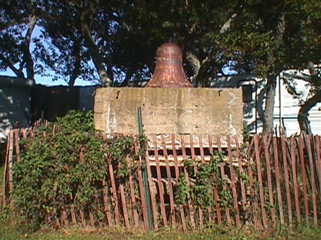
whch was leased from the Blackman family. This pix of the southeast tower
pier is
as it was abandoned in 1917.
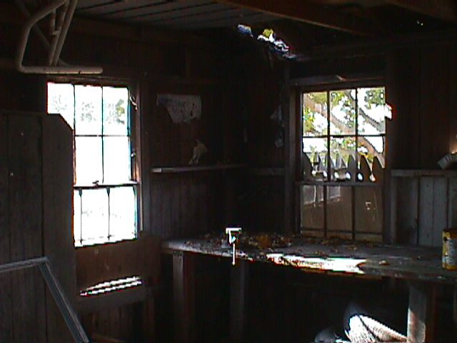
Most recently I found the transmitter
shack not
far from the station off Island Street and both shots are a
match from
the original pix as seen in the Seitz
biography.
The tower
base is
seen here and has been partially protected by a make shift fence.
This is the headquarters today of the Reginald
A. Fessenden ARS - W1FRV
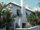
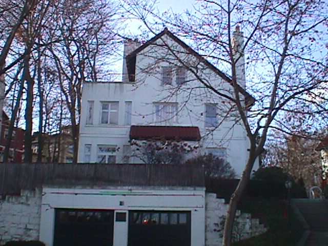
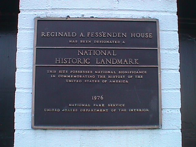
We
traveled to Brookline near Boston and found Fessenden's
house on
Waban Hill Road which has become a Nation
Historic Landmark.
The house seems to be empty and in fair condition...
The reason you have received this e-mail is because you have expressed an
interest in this most august and sublime inventor who made more radio history
than the world is aware. Please pass this on to anyone you may think may be
interested.
To SUBSCRIBE or UNSUBSCRIBE to this occasional e-mail newsletter, please
indicate to raf.nesco
(AT) verizon.net
The
Fessenden ARS is a voluntary association of interested parties. We have no
formal meetings, by-laws, dues, or controllers. We only ask that you be active
to the point of volunteering information and help out as you are directed by
your heart. Your uploads to the Fessenden
web pages
are also appreciated...
Best Regards and 73s from Dave Riley - AA1A - at the Western Tower, Marshfield,
Massachusetts, where the world's first radio voice broadcast took place on
Christmas Eve of 1906....
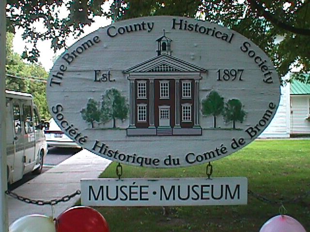
 On August 10th. 2002 at Knowlton, P.Q. on the grounds of the Brome County Historical
Society just north of Newport, Vt. on Canadian Rt-243 was the scene
of a gathering of Fessenden fans for the purpose of swapping information and
telling the world about this most august and sublime inventor...
On August 10th. 2002 at Knowlton, P.Q. on the grounds of the Brome County Historical
Society just north of Newport, Vt. on Canadian Rt-243 was the scene
of a gathering of Fessenden fans for the purpose of swapping information and
telling the world about this most august and sublime inventor...
 Major
domo for the event was Orn Arnason and the group of hams from the Society's
radio club who were on the air all day... Their call is VE2FRV and they are
located topside in the museum along with a most impressive display of early
radio equipment... We got to meet some very nice folks including Clem Beauregard,
VE2BIA, Bill deCarle, VE2IQ, Helmut Hinrichs, Ken, VE2MUX and Terry
Skeats from Bishop's University where Fessy 'himself' attended and
taught...
Major
domo for the event was Orn Arnason and the group of hams from the Society's
radio club who were on the air all day... Their call is VE2FRV and they are
located topside in the museum along with a most impressive display of early
radio equipment... We got to meet some very nice folks including Clem Beauregard,
VE2BIA, Bill deCarle, VE2IQ, Helmut Hinrichs, Ken, VE2MUX and Terry
Skeats from Bishop's University where Fessy 'himself' attended and
taught...
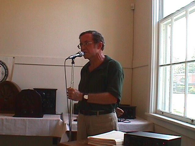
 Terry
gave an in depth talk on Fessenden to a packed house and we all walked away with
more good info and insight...
Terry
gave an in depth talk on Fessenden to a packed house and we all walked away with
more good info and insight...
 The
museum is across the street from the reported birthplace of Reg Fessenden on
Lakeside Drive... We look forward to next year again as we support the
growth of this society and its outreach towards setting the record straight..
The
museum is across the street from the reported birthplace of Reg Fessenden on
Lakeside Drive... We look forward to next year again as we support the
growth of this society and its outreach towards setting the record straight..
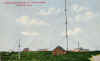
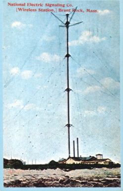
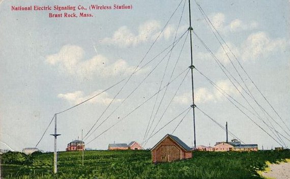
Bluefish Cove, Brant Rock, Massachusetts circa 1905+
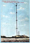
 Reginald A. Fessenden arrives, sets up the National Electric Signaling Co.
and proceeds to make Communications History with many
improvements to the state of the art as known then. Pictured here is a
430 foot Radio tower as used by Fessenden. The ravages of time, the ruthless hand of ignorance have
both laid waste to many
monuments of antiquity but the remains of the original tower base
stands today at Brant Rock as a memorial to such work, much of
which surpassed Marconi, RCA, and other giants of the fledgling
industry..
Reginald A. Fessenden arrives, sets up the National Electric Signaling Co.
and proceeds to make Communications History with many
improvements to the state of the art as known then. Pictured here is a
430 foot Radio tower as used by Fessenden. The ravages of time, the ruthless hand of ignorance have
both laid waste to many
monuments of antiquity but the remains of the original tower base
stands today at Brant Rock as a memorial to such work, much of
which surpassed Marconi, RCA, and other giants of the fledgling
industry..
 Update
01-04
Update
01-04
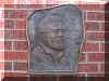
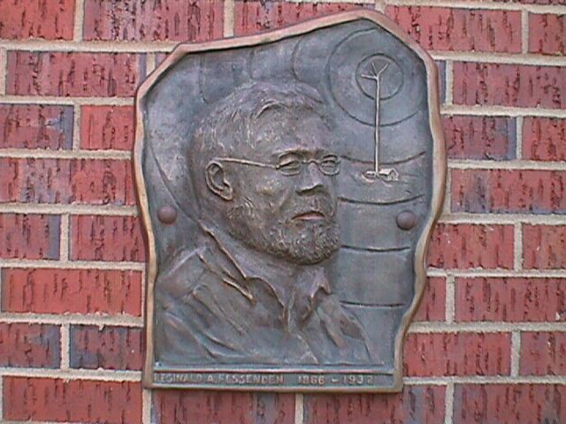
Reginald Aubrey Fessenden (1866-1932)
Hello from Dave Riley, AA1A, in Marshfield, Massachusetts, a
radio enthusiast with good interest in the history of a most advanced
man who possessed a particularly efficient brain, Reginald Aubrey
Fessenden. He ended up with 500+ patents, many of which we find in use
around us every day. I had a chance to visit the records and archives
in Hamilton, Bermuda and see films of him and record his legal affairs
and hear some local word of mouth. He was here in our town from
about 1905 to 1911 or so and had a most turbulent round of successes
and failures with both the scientific and legal communities. His most
remarkable feat here was the World's First Radio Broadcast on Christmas
Eve of 1906 and again on New Years Eve, a week later. . Other firsts
besides voice over radio was the first two way trans-Atlantic
radio communications, first voice heard across an ocean. First to use
'sine waves' in radio as we do today. All the others ended buying
license from him. The Navy took his mind seriously and after the
Brant Rock days he was off to Boston and Underwater Signaling and now
Sub Bases New London and Bangor etc. are as a result of his efforts
much better off...
Canadian born ( 1866 ) in East Bolton, thence to Fergus, Ontario, his roots went back
through the land where Harvard
University stands today as it was John Fessenden's tanning yard in the seventeenth
century who had arrived with the 'Men of Kent'. John apparently never had
children but did send for relatives to come over.
Reg was very young to have entered Trinity College School (15) where he
was always at the top of the class and so remarkable for such a young
age. After some Mastership work at Bishop's College he was well
seasoned in the arts and architectures of the scientific day. At about
17 years, he left school to become Headmaster of Whitney Institute in
Bermuda. As his wife explains, the relatives had strong traits in
medicine, law, merchant, and whom all professed a strong belief in the
Deity. With words like ' Tell the children to serve God with all
Sincerity and Truth ' he grew up in a loving house with prompt
obedience and inspired industry. " This lad is of finer clay " said one
grandfather.
While at Whitney Institute in Bermuda he met his love, Helen
Trott of Hamilton who joined him for a life that rode as a roller
coaster from bare poverty to sure riches but all the while with true
grit and ethic and a particular reverence for the spirit.
He left Bermuda to work briefly for Edison and applied his proof
of inventiveness there while rising from the meter repair division to
Chief Chemist. ( still no wallpaper ) He invented electrical
insulation and tape... He got along good with Edison but tough business
times had caused him to move on, and this future was all to become some
adventure...
The FIRST radio voice actually happened at Cobb Island, MD in
December 23rd of 1900 while he was under contract to the U.S. Weather
Bureau. His objective was to set up telegraph links to provide
remote weather observations but he used some time and effort to explore
and actually produce voice over radio. A radio first. When the
political pawl tried to shake him down ( outside of the contract ), he
left in disgust and pressed on.
The Fessenden's few years of moving into the business environment
brought them to Newark NJ, Pittsfield MA and Pittsburgh PA. During
these moves they met many a wizard of industry and finance.
Taking a chair @ Allegheny College lead him closer to the greatest
academic minds. What a feeling it must have been to have people
like J.P. Morgan, George Westinghouse, Baldwin, and the greatest minds
of the day at close coupling for thought. All this time it was
Reg's main chore to 'crack' the gap between the Electrostatic doublet
theory and reality. His was a mind that could see these things.
He later published a major study of the 'Deluged Civilization' of the
Caucasus Isthmus through the Massachusetts Bible Society. He had the
benefit of being able to catalog voluminous work with one of his
inventions, microfilm...
The 'sharpshooters' were always on his tail and he could not suffer the legal system
well and as a result had left some of his life and health behind in
futile courtroom battle.
His best known radio work was the 'Worlds First Radio Broadcast' made
from Massachusetts along with his many inventions made here... The
First Broadcast was actually a way to save face after the 'hurricane'
at Macrihanish, Scotland had ruined the 420' tower, the likes of which
were also used at Brant Rock. It seems the money backers were on
site to 'hear' trans-Atlantic radio telephone communications with
voice. Brant Rock and Scotland had enjoyed the first two way
trans-Atlantic radio communications by spark telegraph but when the
assistant at the far end actually heard the voice of Adam Stein Jr.
'testing' over the air and over the Atlantic it was sure a time for
ripe investment. Since the Scotland side was in ruin, a 'quick'
alternate idea was to go on the air at Christmas and New Years Eve with
a voice transmission to the general public where radio receivers were
unheard of in the average home. Public broadcasting didn't come
to happen in a large scale until 1921 when KDKA @ Pittsburgh went on
the air with the Harding-Cox debates... KDKA and Brant Rock are
very interwoven by technology and business as was WBZ and the
Westinghouse Electric Corp. with a live and futuristic George
Westinghouse as a Fessenden soul mate....
After many innovations of which we now use daily, he left the
radio invention field to develop underwater sound technology. 'Underwater
Signal' ended up in Groton, Connecticut where untold improvements to the craft
have been ongoing. Adam Stein III was a neighbor here in Kingston,
Mass. who
retired from that company and where his father, Fessenden's Chief Engineer
had built a nice estate on the south side of Silver Lake in the early part of
the 20th century. His daughter still lives in the area. ( Hi Lucy )

 Fessenden retired to Flatt's Village, Smith's Parish, Bermuda and
bought 'Wistowe' which itself hosts a past of a deadly dual during the
1700s to being occupied by our Ambassador ( from Boston ) during the
civil war. Bermuda was sympathetic to the south but that is another
story. I took some pix as Reg had reworked 'Wistowe' and if you
are ever riding from St. George airport area to Hamilton, watch, just
as you go down the peninsular grade into Flatt's Village, look right
and see 'Wistowe', Fessenden's final stop in 1932.
Fessenden retired to Flatt's Village, Smith's Parish, Bermuda and
bought 'Wistowe' which itself hosts a past of a deadly dual during the
1700s to being occupied by our Ambassador ( from Boston ) during the
civil war. Bermuda was sympathetic to the south but that is another
story. I took some pix as Reg had reworked 'Wistowe' and if you
are ever riding from St. George airport area to Hamilton, watch, just
as you go down the peninsular grade into Flatt's Village, look right
and see 'Wistowe', Fessenden's final stop in 1932.
He is buried in 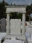 Saint Mark's Church Cemetery across
the street from the Church and Rectory in Smith's Parish.
Saint Mark's Church Cemetery across
the street from the Church and Rectory in Smith's Parish.
On his grave between
the ancient columns is inscribed:
" By his genius distant lands converse and men sail unafraid upon the
deep "
Hieroglyphics are also inscribed and are roughly translated to mean:
" I am yesterday and I know tomorrow...
"
What he said of himself:
My parents despaired of me. They saw my future as a church
minister or a teacher, but when I closed my eyes and dreamed, I
saw an invention that could send voices around the world without
using wires or cables. "There's no future in that," my
mother told me, and she was both right and wrong.
In my lifetime, I developed hundreds of inventions including the electric gyroscope, the heterodyne, and
a depth finder. I built the first power generating station at
Niagara Falls and I invented radio, sending the first wireless
voice message in the world on Dec. 23, 1900.
But despite all my hard work, I lived most of my life near
poverty. I fought years of court battles before seeing even a
penny from my greatest inventions. And worst of all, I was
ridiculed by journalists, businessmen, and even other scientists,
for believing that voice could ever be transmitted without using
wires. But by the time of my death, not only was I wealthy from
my patents but all of those people who had laughed at my ideas
were twisting the dials on their newly bought radios to hear the
latest weather and news.
* Like Michael Dell and Bill Gates, he never finished
College..
A Voice in the Air...
Here is a reference from the latter Pittsburgh days and the KDKA gang.
In 1893 Professor Reginald A. Fessenden came to Pittsburgh to serve as the
head of the electrical engineering department at Western University (now the
University of Pittsburgh.) While here, Fessenden read of the radio experiments
that Guglielmo Marconi was conducting in England and began experimenting himself
at a lab at Allegheny Observatory. Marconi's system could only transmit and
receive dots and dashes--Morse code. But Fessenden's goal was to transmit the
human voice and music.
To accomplish this he devised the theory of the "continuous wave"--a means to
superimpose sound onto a radio wave and transmit this signal to a receiver where
the radio wave would be removed, leaving the listener with the original
impressed sound.
(The continuous wave is the electronic basis that make radio and television
transmission possible.) Fessenden later put the theory into practice and made
the first long-range transmissions of voice on Christmas Eve of 1906 from a station
in Brant Rock, Massachusetts. Astonished ship radio operators hundreds of miles
out in the Atlantic heard the voice program.
Although Fessenden's work made voice radio possible, it would take 10 years
and the First World War before it became common place. Throughout this period,
radio was still seen primarily as point-to-point communication between
transmitting stations, a sort of "wireless telephone." The notion of
"broadcasting" or transmitting to an audience of listeners was not seen as
practical. Radio at that time was used mostly for commercial shipping purposes,
but land based amateur operators began to appear as electronics technology
improved.
Brant Rock Highlights:
- Tower completed December 1905
- 2 way transmissions between Scotland January 1906
- First Public Voice Broadcast on Christmas eve of 1906 and a week
later on New
Years Eve
- Voice demonstrations between Brant Rock and Plymouth - heard
as far away as Guantanamo Bay Cuba - Voice eventually heard in
Scotland
- Locals remember day tower dismantled in 1917
- Brant Rock Inventions include the electrolytic
detector, heterodyning , alternator development,
efficiently tuned antenna circuits and 'Continuous
Waves'..
Meeting at M.I.T. June 1994
The Fessenden electro-acoustic oscillator,
and performance estimate.
The first practical man-made sonar oscillator, conceived and
designed by the Canadian Reginald A. Fessenden, was a 540-Hz air-backed
electro-dynamic driven clamped-edge circular plate. Work on the
oscillator started in 1912 while Fessenden was working for the
Submarine Signal Company, Boston, MA. In January 1914, in Boston
Harbor, underwater communication was first shown by using a Morse code
carrier to modulate the oscillator, thus demonstrating a means of
ship submarine acoustic communication. In March of 1914 the
oscillator was tested aboard the U. S. Coast Guard cutter Miami on the
Grand Banks off Newfoundland Canada, where echo ranging from a 3200-m
distant iceberg and depth sounding were demonstrated. In 1915, the
oscillator was even tested at 100 kHz. The Fessenden oscillator models
(ca. 500, 1000, and 3000 Hz) were so successful that they were used
until, and during World War II for sonar and mine detection purposes.
Despite these landmark achievements, at that present no oscillators
were known to exist, and no modern acoustic measurements have ever been
made to establish the acoustical performance. To partially fill in this
gap, the Fessenden oscillator will be described and an electro-acoustic
model will be used to predict the acoustic performance.
* He won the Scientific American's Gold Medal in 1929 for
the fathometer which could determine the depth of water under a
ship's hull. Fessenden eventually held 500 patents.. Some other
milestones include the invention of turbo-electric drive for
battleships, insulating electrical tape and many other underwater
sound devices..
Beginning in 1898, Reginald A.
Fessenden worked to develop a complete radio transmission and receiving system
which didn't infringe on any competitor's patents and could also transmit audio,
not just dots-and-dashes. Fessenden was ultimately successful, and on December
21, 1906 gave a demonstration of the new alternator-transmitter to invited
representatives from a number of organizations. However, the main target was the
American Telephone & Telegraph Company, whose review of the test appeared as
a front page article in The American Telephone Journal, an AT&T publication.
Fessenden and his financial backers dearly hoped AT&T would be so impressed
it would buy the rights to the patents which covered the new system. The outcome
of this presentation is reviewed at the close of this article.
This
AT&T review noted that wireless telephony was "admirably
adapted to the transmission of news, music, etc." simultaneously to multiple
locations. Three days after the presentation reviewed in this report, on the
evening of December 24, 1906, Fessenden would use his new alternator-transmitter
to give what is generally considered to be the first broadcast of
entertainment by radio, as part of the ongoing promotion of the new system.
One item of interest is that this demonstration took place in the middle
of winter. The review mentioned the "lack of
susceptibility to the foreign influences which produce disagreeable noises",
but had the test taken place in the summer, they would have heard a tremendous
amount of static whenever there was a passing thunderstorm due to the station's
extremely low operating frequency.
Engineering, January 18, 1907, page 89:
TRANS-ATLANTIC WIRELESS TELEGRAPHY.
IN 1904 the National Electric Signalling Company decided
to erect two stations for trans-Atlantic working, the antennæ to consist of
cylindrical steel tubes, 400 ft. high, with the National Electric Signalling
Company's patent umbrella capacity at the top, each tube to rest at the bottom
on a pivoted insulated base, and to be supported by sectionally insulated
wire-rope guys of the company's standard type. This type of antennæ, which was
invented and designed by the National Electric Signalling Company, and patented
by it, has proved quite successful, and has been copied in Germany at the Nauen
wireless station, a lattice-work, however, being used instead of a steel
cylinder.
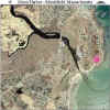
The sites selected were Brant Rock, 30 miles south of
Boston, Massachusetts, U.S.A., and Machrihanish, on the far side of the Mull of
Cantyre from Campbelltown, Scotland. These two points were selected because the
great circle joining them passes up the Bay of Fundy, over the Isthmus of
Chignecto, and across Newfoundland at a point where it is comparatively low. The
contract for the steelwork and erection of these towers was let to the Brown
Hoisting Machinery Company, of Cleveland, Ohio, U.S.A., and for the insulators
to the Locke Insulator Company, of Victor, N.Y., U.S.A. Owing to delays on the
part of the contractors, the towers were not completed until December 28, 1905.
On Friday, December 29, 1905, Brant Rock sent to
Machrihanish, but nothing was received, owing, as it was afterwards learned, to
a miscalculation in the wave-length. On January 2, 1906, Brant Rock sent again,
and Machrihanish received the messages. Communication was maintained one way
until about the middle of January, when, the sending apparatus at Machrihanish
having been completed, Machrihanish sent, and Brant Rock received messages from
there at the first trial. Very satisfactory communication was then maintained
for some time, and code Messages containing as many as forty cipher words were
received without a single error, or the necessity of any repetitions.
It was found that the amount of atmospheric absorption
had been miscalculated. From tests made on shipboard at distances of 1500 miles,
the atmospheric absorption had been found to be about 90 per cent.--i.e.,
10 per cent. of the radiation got through. It was considered that, by assuming
the atmospheric absorption to be 99 per cent.--i.e., that 1 per cent. of
the radiation got through--a sufficient factor of safety would be provided. As
the design was conservative, it was found that in practice the factor of safety
was larger than this, and equivalent to an absorption of 99.8 per cent.--i.e.,
that messages could be received although only one-fifth of per cent. got
through. Over this distance of 3000 miles, partly over land, it was found that
the absorption was considerably greater than this, and that as a matter of fact,
during daylight, not more than one-tenth of 1 per cent. of the energy got
through, and that a factor of safety of at least 100,000 must be provided.
As an illustration, with the same sending power, on some
nights messages were received 480 times stronger than was necessary for
audibility, and the messages could be read with the receiver 6 in. away from the
ear. On other nights with the same sending power the messages were so faint that
they could not be read. A number of tests were made, which were witnessed by
scientific experts from the General Electric Company in America, and Mr.
Shields, the technical expert of Messrs. Abel and Imray, and others; but as it
was evident that the stations were not sufficiently powerful for commercial
work, they were shut down early in 1906, for reconstruction.
Owing to the impossibility of getting aluminium for the
compressed-air condensers the stations were not opened again until October,
1906, when they were operated at a factor of safety of 2000, only half of the
condensers being in place. With the full amount of condensers the factor of
safety would have been 4000, and a new form of receiving apparatus, which it was
intended to use, would have brought up the factor of safety to 400,000. The
stations operated continuously, barring shut-downs for a couple of nights for
mechanical reasons, until December 5, when the tower at Machrihanish blew down.
This accident came at a very unfortunate time, as work had just been begun on a
new method for eliminating the atmospheric absorption, which had given very
promising results, the absorption having been already reduced to one-tenth of
what it was formerly. Moreover, the new receiving apparatus had only been partly
installed, and no opportunity had been afforded of trying it between the
trans-Atlantic stations.
The specifications on which the contractors bid called
for the tower to stand a wind-pressure of 50 lb. per square foot on a flat
surface, and for the tower to be capable of being extended to a height of 500
ft. later, if desired, and to be capable of standing a pressure of 50 lb. per
square foot on a flat surface even if one set of guys broke.
The design was carried out in a very creditable manner
by the Brown Hoisting Machinery Company. In a future issue we shall illustrate
the installation and describe the jointing of the guy-ropes, to the failure of
which the fall of the mast is attributed. This jointing was carried out by a
subcontractor.
The American Telephone Journal, January 26, 1907, page 1:
Experiments and Results in Wireless
Telephony
BY JOHN GRANT
WIRELESS
transmission of speech over a distance somewhat greater than ten miles was
satisfactorily accomplished in the presence of a number of persons invited to
witness demonstration of a new system of wireless telephony at the experimental
station of the National Electric Signaling Company, Brant Rock, Mass., on Dec.
21st, 1906.
The representative of THE AMERICAN TELEPHONE
JOURNAL who was present at these tests was furnished by
Professor Reginald A. Fessenden, the inventor of the system, with many facts
which have made it possible to trace in the present article the development of
his work. For this purpose abstracts without quotation will be freely made from
an article which has been furnished by him for publication in Electrical
Review, London, and from descriptions embodied in United States patents
which have already been issued.
Speaking broadly, wireless telephony by
this system is accomplished by generating a practically continuous
succession of electromagnetic waves, modifying the character of the
emitted impulses by means of sound waves without interrupting their
continuity, and receiving them in a constantly operative receiver of
suitable form which controls a local circuit containing a battery and a
telephone receiver. The apparatus which was seen in successful use at
the time of the recent tests is the result of a series of diligent
investigations in which a large amount of work was done to show the
necessity of rejecting plans which did not lead to the required quality
of transmission.
Beginning his work on the subject in 1898, Professor
Fessenden made some experiments which were entirely unsuccessful. At this time
the only recognized means for the practically continuous generation of
electromagnetic waves capable of being propagated through space to affect a
distant receiving instrument were:
(a) The plain aerial with spark gap used
by Marconi.
(b) The plain aerial heavily
loaded with inductance, used by Lodge.
(c) The plain aerial in conjunction with
a local oscillatory circuit having a period of a different order of magnitude
from the period of the antenna, used by Braun.
Lodge's method was found to be the only one adapted
to produce prolonged trains of waves. Tietz at an early date had used Leyden
jars connected across the spark gap, and later Braun described and used a Leyden
jar and antenna sending circuit in which the natural period of the Leyden jar
circuit was specified as of a different and lower order than that of the antenna
circuit. [Braun, English patent No. 1,862, A. D. 1899]
None of these methods, however, gave the results
desired. Professor Fessenden conceived the idea that good results could be
obtained in conjunction with a local circuit tuned to the same frequency as the
aerial. [U. S. Patent No. 706,735]
This method,
used by him in association with Professor Kintner, proved to give a fairly
satisfactory means of producing a long train of waves, and is now extensively
used. After making various tests with a Wehnelt interrupter and other devices
with which more or less encouraging results were obtained, an induction coil and
commutator were settled upon as a make and break mechanism for the tuned
circuit. With this circuit, and apparatus giving 10,000 sparks per second, the
experiments in wireless telephony led to the transmission of speech, which was
first accomplished in the Fall of 1900.
The antennae were two masts, 50 feet high, set up one mile apart at Rock Point,
Md. A commutator making 10,000 breaks per second in circuit with an induction
coil was used for generating waves.
In these
experiments the articulation was of a sort which left considerable room for
improvement, and there was a noise, due to the irregularity of the spark, which
was disagreeable and at times overpowering. This lead to the invention of the
compressed gas spark gap, [U. S. Patent No. 706, 741] which gave a steadier
spark. This device is essentially a spark gap having its terminals, 4, 5 (Fig.
1), enclosed in a chamber in which the gas may be subjected to a pressure
produced by the pump 8. This spark gap is connected between the ground and the
antenna, shunting the source of energy, the circuit of which contains a make and
break device. In practice the chamber was filled with compressed air, from which
the oxygen was absorbed by lime in the bottom of the chamber, leaving compressed
nitrogen. The appearance of the exterior of the apparatus is shown in Fig. 2.
Later a mercury gap of the Cooper-Hewitt type was used, but with this the
results obtained were not quite as good as with the compressed gas gap, even
when the spark was localized as much as possible by small points of
platinum-iridium wire projecting to the surface of the mercury.
With these types of apparatus high
speed breaks of various kinds were used. In 1901 and 1902 experiments were made,
using Elihu Thomson's method of producing rapid oscillations by means of an arc
and shunted resonant circuit. Better results were obtained by a modification of
this method, using regulating resistance, compressed gas gaps and governing
circuits for the purpose of making it more applicable to practical working, but
there was still a very considerable amount of foreign noise in the telephone
circuit.
Work on high frequency alternating current
dynamos had been begun in 1900, and in 1902 an alternator giving 10,000 cycles
per second was completed at the works of the General Electric Co. and delivered
to Professor Fessenden. This was a 1 kilowatt machine, delivering about 10
amperes at 100 volts. With it was used an air core transformer giving about
10,000 volts, and an interrupter producing 20,000 sparks per second. It was
necessary to use the spark gap, as the frequency of the machine was not high
enough for the direct production of electromagnetic waves. This combination,
however, on account of the regularity of its action, gave much better results
than the rotating break, and measurements made in Washington in 1904 led to the
belief that transmission could be effected over a distance of 25 miles.
Continued experiments were made with spark gap
apparatus of various types, and in many cases fairly good articulation was
obtained. With all these types of apparatus, using a spark gap however, while
radiation was sufficiently continuous for the transmission of speech, it became
more and more evident that the quality of articulation demanded for commercial
telephony could not be obtained without a source of power which would give
completely continuous radiation. Among the many methods for obtaining this which
were tried was the very interesting method of producing high frequency
oscillations commonly known as the musical arc, using a continuous current arc
shunted by a condenser and inductance in connection with a magnetic blow out,
invented by Professor Elihu Thomson.
Professor
Fessenden as early as 1898 had by his experiments verified the statement made by
its inventor [In U. S. Patent No. 500,630] that frequencies as high as
50,000 or more can be obtained in this way. This statement, it is interesting to
note, was controverted as late as 1903 by Duddell, [London Electrician, Vol. 51,
Page 902] who seems to have not fully grasped the method of operation of the
device, although many European scientists have even incorrectly attributed its
invention to him.
The experiments
made with this method of producing oscillations showed it to be hardly
satisfactory. By the use of properly cooled electrodes and an air blast and
magnetic blow out, very high frequencies were obtained, but it was found that
neither frequency nor intensity was constant. The fact that a key could not be
used to make and break the circuit, since the arc would not start itself, made
it impracticable in its original shape.
In order to
overcome the difficulties arising from irregularity, the plan was modified by
the substitution for a pure inductance in series with the arc of a coil having a
considerable resistance with only a moderate amount of self-induction. This
resistance was so adjusted and proportioned to the shunt resonant circuit as to
maintain the frequency almost absolutely constant. [U. S. patent No.
730,753.]
In Fig. 3 the coil 59 is shown in series
with the arc in the sending circuit. It is so designed as to have a high
resistance but low inductance, and any suitable means, such as a plug, 60, may
be provided for shunting out more or less of the resistance. In operation, when
condenser 12a has been charged to a sufficient potential, there will
occur a discharge across the spark gap, discharging the condenser and setting up
oscillations in the sending conductor. On account of the high resistance, 59,
some time is required to recharge the condenser to sparking potential. The
discharge is therefore intermittent, and may be made to occur many times per
second as is desired, within recognizable limits, by plugging out more or less
of the resistance. With this apparatus the periodicity depends upon the
discharge voltage, which is not liable to fluctuate.
To overcome the difficulty arising from the
inability of the arc to start itself, a method of working was devised in which
the arc operated continuously, and emitted radiation continuously, and the
signaling was done by altering the frequency of the emitted waves. [U. S.
patent No. 706,742]. Numerous experiments looking to the adaptation of this plan
to telephony were made, but it was found that by none of the arrangements tried
could the scratching and hissing noises in the receiver be eliminated. While
these experiments were being carried on, work on the development of a new high
frequency dynamo was making good progress. In the only patent which has yet been
granted on this machine [U. S. Patent No. 706,737] its general
characteristics are described as follows:
It is
necessary that it should give a pure sine wave, as such a form is the only one
adapted to give perfect resonance. With a dynamo giving such a curve forming a
part of a suitably constructed sending conductor, Professor Fessenden asserts
that if the machine be wound to give a thousand volts on open circuit, it is
possible by means of resonance effects to obtain a voltage of 100,000 volts on
the sending conductor. These resonance effects are obtained by using a dynamo of
low internal resistance as a portion of the sending conductor of large capacity
or self-induction, or both, having these electrical constants suitably
proportioned to give to the sending conductor, that is, to the whole conductor
from the top of the antenna to the ground, including the armature of the dynamo
itself a natural period identical with the periodicity of the dynamo. If the
frequency of the dynamo were to be made lower than the periodicity of the
radiating circuit the chief effects would be electrostatic and magnetic in their
nature, and there would be practically no electromagnetic radiation. As it is
only energy in the form of electromagnetic waves which may be transmitted to a
great distance through the atmosphere, it is highly important that this effect
should be predominant. The armature must have a low resistance, because if of a
high resistance the oscillations will be dampened, making it impossible to
produce high resonance voltages. Ventilation must be good, as the current may
run up to a very high figure. The length of wire in the armature must be as
small as possible, compared with the length of the sending conductor. If this
relation were not maintained, the electrical constants of the entire sending
conductor would be determined too largely by that part of the circuit between
the armature terminals, and the amount of radiation would be much less than would be the case if the
armature had a relatively small length of wire. Another way of stating this
requirement is that the self-induction and capacity of the armature must be as
small a fraction as possible of the self-induction and capacity of the entire
sending conductor in order to secure the highest radiating efficiency. It is
also essential that all iron magnetically influenced by currents in the
conductor should be so proportioned and distributed as not to affect the shape
of the curve of voltage, or to cause loss of power by hysteresis, as in such a
case there would be too much dampening. For these reasons the dynamo may be
constructed with a fixed armature containing no iron, having the air gap as long
as possible, consistent with a high magnetic flux density, and revolving pole
pieces so shaped as to produce sine waves as closely as possible. The revolving
parts may be formed of magnetic material of high tensile strength, such as
nickel steel. A peripheral speed of five miles per minute, which can be safely
maintained with properly constructed moving parts of nickel steel, would allow
the machine to be arranged to give one hundred thousand cycles per second. Such
a speed can be obtained with a steam turbine to drive the dynamo.
The alternator which is at present in use is
constructed along those lines, but embodies many ingenious mechanical
arrangements due to the skill of several of the engineers of the General
Electric Company, notably Dr. Steinmetz, Mr. Haskins, Mr. Alexanderson, Mr.
Dempster, and Mr. Geisenhoner.
This
machine (Fig. 4) was originally designed for a frequency of 100,000
cycles, at an output of one kilowatt. It is now being driven by
belting, the construction of a type to be driven by a De Laval turbine
connected through gearing, and, on account of belt slipping, is never
run at a speed to give more than 80,000 cycles. For most work it is run
at 60,000 cycles, at which speed it has an output of about one-quarter
of a kilowatt. The internal resistance of the armature is approximately
six ohms, and the inductive drop at full load is about equal to the
ohmic drop. At 60,000 cycles the voltage is about 60 volts. The
armature makes 10,000 revolutions per minute, bearings being kept at a
low temperature by lubrication controlled by oil pumps. The operation
of the machine is said to be extremely satisfactory, it having been run
daily for six or seven hours at a time with practically no attention.
The design, and the method in which it has been worked out by the
engineers and mechanics of the General Electric Company, mark a notable
advance in dynamo-electric machinery, for which the highest credit is
due those who have developed this machine, accomplishing what has been
declared by Fleming, in his latest published work in wireless
telegraphy, to be an impossibility. (To be continued.)
February 2, 1907, page 1:
MODIFICATION of the
character of the electromagnetic waves to impart the fluctuations characteristic
of the current in a circuit containing an ordinary telephone transmitter has
been the object of an exhaustive series of experiments by Professor Fessenden,
second only in importance to those which led to his development of a
satisfactory system for radiating energy. It is evident that the forms of the
electromagnetic waves must be varied exactly in correspondence with the sound
waves of spoken words at the transmitting station, and at the receiving station
the apparatus must be capable of transforming the energy into sound waves of
like character to those originated at the distant end of system. An early
arrangement tried at the transmitting end of the line was of the form indicated
in Fig. 5. [U. S. Patent No. 706,747] Here the conductor from the aerial
passes through a winding 2 of the transformer 3 to the source of energy (here
represented by induction coil the other terminal of which is connected by
induction coil 6), the other terminal of which is connected to ground. Capacity
18 and in inductance 19 in series shunt spark gap 4-5 for the purpose of
maintaining constant frequency, as previously described with referenced to Fig.
3. Transmitter 9 and battery 8 are serially included with a second winding 7, on
transformer 3. Capacity 18 and inductance 19 are arranged to have the same
period of oscillation as the sending conductor 1, and also as the receiving
conductor. Advantage of the fact that if the resistance of a transformer
secondary be changed it alters the inductance of the primary is taken to produce
the required modifications the waves emitted. Thus by speaking into the
transmitter the permeability of the core 3 is correspondingly modified,
producing a change in the self-inductance of the winding 2. This in turn affects
the natural period of vibration of the sending conductor, throwing it out of
resonance with resonating circuit 18-19. Owing to this variable failure of
resonance there is produced a series of corresponding changes in the intensity
of the waves given off by the conductor 1, and these variations are reproduced
in the circuit of the receiving conductor. It is to be noted that the essential
point in the operation of this method of transmission is the throwing of the
aerial out of tune with the resonant circuit 18-19, and an alternative method of
doing this is to alter the capacity of conductor 1, instead of its inductance.
To affect this type of variation, conductor 1 was connected to a fixed condenser
plate 13 (Fig. 6), while plate 14 is formed by or connected to a diaphragm
capable of vibrating in unison with sound waves, produced by words spoken into a
transmitter mouthpiece. The latter arrangement has been termed by Professor
Fessenden a "condenser transmitter." Relating the practical results obtained
with this type of apparatus in conjunction with the high frequency dynamo for
generating waves he states that with a diaphragm two centimetres in diameter a
movement of 1-100 of an inch inwards reduced the current from 3.1 amps. to 2.5
amps. This result was obtained on a circuit used for telephoning from Brant Rock
to Plymouth, a distance of about ten miles. The dynamo was connected to the
aerial through a transformer with 10 and 100 turns respectively, stepping up the
voltage from 45 volts to approximately 3,000 volts, with a frequency of 50,000
cycles. This result was obtained without a resonant circuit between the movable
terminal of the condenser transmitter and ground.
In Fig. 9 is shown
a third arrangement using a carbon microphone transmitter, 16-17, in circuit
between the sending generator 15 and aerial 1. A proper type of transmitter for
this purpose should be capable of carrying from 10 to 100 amperes. In the
practical instrument which has been developed the metal enclosing the carbon
chamber is made with two deep circumferential grooves, visible in Fig 11,
permitting the rapid radiation of such heat as may be produced.
In operation, the sending conductor has its natural
period in resonance with the period of the dynamo, and the amount of resonant
voltage depends upon the resistance of the microphonic contact. Speaking against
the diaphragm therefore causes the voltage at the aerial terminal to change in
correspondence with the sound waves. This microphonic contact may be substituted
for the variable inductance or variable capacity in conjunction with the
resonant circuit 18, 19 as shown in Figs. 5 and 6. While the condenser
transmitter has given the best results, the carbon transmitter works very well
in practice. The instruments as now constructed have platinum-iridium
electrodes, and carry three amperes without injurious heating. To get the best
results the ohmic resistance of the carbon transmitter should be equal to the
radiation resistance of the aerial. In practice the carbon transmitter is
usually placed between the exciting source and ground, as shown in Figs. 12, 14,
for the purpose of preventing possible shocks.
A
carbon transmitter may also be placed in the field of the high frequency
alternator. Still another method is to use the armature winding differentially,
with a second field, to shift the position of the field. Many other forms of
transmitting devices for varying the natural period of the sending aerial
circuit through the action of a transmitter upon a spark gap, etc., were
experimented upon, but were laid aside on account of the objectionable noises
which they produced in the receiving circuits.
Receiving
apparatus at the time Professor Fessenden began his work was in
an unsatisfactory state, all known forms of receiver being of the
"imperfect contact" type. These were not considered satisfactory, as it
is well established that a receiver adapted to reproduce speech must be
constantly operative. Moreover the known types were all voltage
operated devices, and the thing required was recognized to be a current
operated receiver. Forms of current operated receivers were devised, to
the number of more than one hundred. In all these the fundamental
principle is that all constants are electrically good contacts, and the
devices are capable of being operated by electromagnetic waves.
[U. S. Patent No. 706,736] They are broadly distinguished from
devices depending for their operation upon the varying of contact
resistance, as in the "coherer" types of receiver. Amongst these types
of receiver which have become known may be mentioned the hot wire
barreter, the liquid barreter, the eddy current receiver, the
mircobaric receiver, the repulsive disk, etc. Of these the most
satisfactory for telephone work was found to be the liquid barreter.
The type of instrument consists of a small vessel containing a liquid
in which is immersed a diaphragm perforated with a minute hole, before
which is placed a fine point connected with the antenna. Under the
action of the electromagnetic waves the stratum of liquid contained in
the perforation of the diaphragm becomes heated, its resistance is
varied, and if the terminals be shunted by a battery and receiver
sounds will be produced corresponding to such fluctuations in
resistance. The inventor of these various forms of receivers believes,
however, that they are all surpassed by what he terms his "heterodyne"
receiver. Although this cannot be fully described on account of the
condition of patents, the following data are available:
All forms
of voltage operated receivers, and most forms of current operated receivers are
very inefficient. Even the liquid barreter, which is recognized as an
exceptional sensitivity instrument has an efficiency of only about 1-10 of one
per cent for weak signals. The magnetic receiver of the types developed for
wireless telegraphy is in the same class. While a liquid barreter or magnetic
receiver will give an indication between 1/100 and 1/1000 of an erg., an
ordinary telephone will indicate the passage of less than 1/1,000,000 of an erg.
From this it is evident that a proper method for directly using an ordinary
telephone receiver would increase the efficiency enormously. This has been
accomplished in the heterodyne receiver, which is a combination of the "beats
method," [U. S. Patent No. 706,740] and the method of operating by
continuously generated waves, [P. P. S. Patent No. 706,737] which has
already been described. The beats method requires the use at the sending station
of two or more antennae, so constructed and proportioned as to have different
periods of oscillation--in practice a difference of about 5 per cent being
preferred. At the receiving station two or more conductors are connected to
separate windings and of a receiver magnet. Separate alternators are used, tuned
to frequencies corresponding with the periods of the aerials to which they are
respectively connected. As the device is operated waves of different
periodicities are generated by the respective sending conductors, and these
waves produce in the corresponding receiving conductors correspondingly varying
oscillations in potential. As the oscillations persist there follows a varying
difference of potential at the receiver terminals, and corresponding signals
caused by the electric "beats," analogous to sound "beats" will be heard. The
heterodyne receiver (Fig 8) is built up of a telephone having a fixed magnetic
core formed of iron wires .001 inch in diameter, and this core is excited by a
high frequency current. A small coil, with or without a core, is cemented to a
thin mica diaphragm, and this coil is arranged to be excited by the oscillations
produced by the received electromagnetic waves. While it is impossible to make
the frequency of waves generated at the sending station exactly equal to the
oscillations generated at the receiving station, it is believed that regulation
sufficient for all practical purposes may be obtained by automatic means. This
gives an extremely efficient form of receiver. Advantages pointed out by the
inventor of this type of receiver are that it is unaffected by atmospheric
disturbances, or by disturbances from nearby stations, and that it is adapted to
the reception of a message on the same aerial which is being used to transmit a
message to another station.
The apparatus as set up
for experiments in talking from Brant Rock to Plymouth at the time of the recent
test referred to at the opening of this article was set up in conformity with
the circuits shown in Figs. 12 and 15. The armature in the transmitting circuit
Fig. 12 is in series with a resistance and the primary of a variable
transformer. This latter piece of apparatus consists of a pair of non-inductive
cores, about which are wound a number of turns of wire, the number of turns on
each core being varied to suit the requirements of transformation by the simple
device of rotating the core with a crank. Examples of this type of transformer
are visible at the front of the right hand table in Figs 7, 10, and in Fig. 13.
A similar transformer is used in the receiving circuit, Fig. 15. The receiver
and battery are connected across the terminals of the barreter in the manner
indicated, a simple potentiometer arrangement being used to regulate the normal
voltage at the receiver terminals. Inductances, not shown in these diagrams,
were inserted between the aerial and the transformer winding for the purpose of
tuning. With this arrangement of apparatus speech was clearly transmitted from
Brant Rock to Plymouth by some of the men present at the tests made on December
21. These tests also included experiments in transmission from a phonograph and
nearly all speech, as well as music was distinctly intelligible. All tests made
were apparently satisfactory. Articulation was distinct, the quality of
reproduced tones good, and the efficiency of transmission was high. An expert
stated that he believed efficiency to be on that day rather better than
transmission through twenty-five miles of standard cable, this judgement being
of course, based on his estimation unassisted by any of the devices for
comparison which are available in laboratories for transmission testing. A
modification of the circuit which is shown in Fig 12 is effected by the
introduction of a telephone in Figure 14. For this purpose Professor Fessenden
has designed a highly ingenious type of relay, using differential windings on
the cores of magnets, between the poles of which is mounted an armature attached
to the electrode of a microphonic transmitter chamber. Variation in the current
traversing the windings causes a shifting of the magnetic field one side or the
other, producing a corresponding series of changes in the position of the plate
controlling the movable transmitter electrode. This relay has shown itself to be
very sensitive in practice, but improvements made within the past few weeks are
expected to materially improve its efficiency. As a call a double differential
relay of this type has been used to operate either a loud-speaking transmitter,
a bell or a Morse writer.
In the system shown it is
necessary, as in the early Bell telephone system, to throw a switch to change
from talking to listening. At the tests a method of overcoming this defect was
explained. Although patent considerations prevent the publication of the method
of accomplishing this at the present time, it has been in successful operation.
In general, Professor has found that where no spark is used for transmitting and
a carbon transmitter is used for modifying the strength of waves the speech is
as distinct as over a short open wire and rather more distinct than over cables,
owing to the absence of any capacity effect, and there is a total absence of
extraneous noise. With the present methods of transmission, there appears to be
no distortion of sounds with increase of distance, as is found in all wire
lines. Although this might have anticipated, it has been experimentally
demonstrated by comparison of the relative intensities of notes of different
frequencies at different distances. These characteristics have led to the
prediction that wireless telephony may operate over longer distances than is
possible with wire lines. The difficult problem in increasing the range of
transmission is at present the modulation of the large amount of energy given
out by the antenna. Where an ordinary granular carbon transmitter is used about
one-half ampere of current is all that can successfully be modulated and even
with special transmitter buttons 2½ amperes seems to be about the limit. With
multiple buttons the limit is reached at about 10 amperes. For currents larger
than ten amperes a number of telephone relays may be placed in series and
operated by a single transmitter. The practical limits for this method have not
as yet been determined. Much depends upon the possible improvements in the
efficiency of the relays.
Possible uses of wireless
telephony cover a variety of important fields. At sea the wireless telephone may
be used as a safeguard in foggy weather. On land it is doubtful if wireless
transmission will ever supplant the local exchanges with wires. So far as the
subscriber is concerned, the simplicity of present systems is an advantage which
is not likely to be overcome. For trunking however, it apparently has a field,
owing to its comparatively low first cost, faculty of working multiplex for the
transmission of several conversations simultaneously by methods which are now
being developed, and to its lack of susceptibility to the
foreign influences which produce disagreeable noises in open wire lines. Its
ultimate adaptability to long distance transmission and its comparative low cost
is a factor which should not be overlooked. For supplanting submarine cables the
system has an obvious advantage in transmission owing to the absence of capacity
effects. A practical application along this line which has been suggested is the
use of the wireless system for transmitting speech across the English Channel.
It is admirably adapted to the transmission of news, music,
etc. as, owing to the fact that no wires are needed, simultaneous transmission
to many subscribers can be effected as easily as to a few.
Methods of automatic relaying from ordinary
telephone lines to wireless transmitting lines and from a wireless receiving
station to a wire line are obviously simple and have already been tested with
success. On sea and on land wireless telephony has the immense advantage over
telegraphy that no expert operator is required either for transmission or for
sending.
Unfortunately for Fessenden and his backers, AT&T decided --
correctly -- that Fessenden's system, while revolutionary, was not yet refined
enough for commercial telephone service, and so did not purchase the patents. It
would not be until 1920 that the first U.S.
telephone link by radio would be installed, at Catalina Island, California.
And although the equipment used by the Catalina link was based on the same basic
principles -- continuous-wave AM signals -- first developed by Fessenden's 1906
Brant Rock station, instead of alternator-transmitters and liquid barreter
receivers, the Catalina link would employ vacuum-tube transmitters and
receivers, which had been developed in the interim and were much more efficient.
Fessenden had a falling-out with his backers, and eventually
left radio work. But the alternator-transmitter continued to be
developed by General Electric, under the supervision of Alexanderson's
Alternator-transmitters, because of their complexity, high cost, and
limited range of frequencies, would never be employed by broadcasting
stations, but they did make superb longwave radiotelegraph
transmitters, and would be used for transoceanic service through the
nineteen-forties. In fact, by 1919 the alternator-transmitter patents,
with their application for international radiotelegraph service, would
be considered so valuable that the question of their ownership
triggered the formation of the Radio Corporation of America, because
for national security reasons the U.S. government didn't want the
British-owned Marconi company to gain control of the
alternator-transmitter rights.
ref:
Fessenden, Builder of Tomorrows by Helen Fessenden,
Coward McCann, 1940
Radio's First Voice by Ormond Raby, MacMillan of
Canada, 1970
The Chronicle's and pot bellied stove yarns of Harold
Mansfield, late of Plymouth
The lovely voice of his maid lady of many years, 95 years young and very nice
Reg's Chief Engineer's son, Wor. Adam Stein, III of Kingston now
passed
Latest
Link findings:
John Jenkins collection of Vintage Radio and Scientific Apparatus... http://www.sparkmuseum.com/RADIOS.HTM
John Dilks radio
history... http://www.eht.com/oldradio/history/outline/hoganbio.html
John Dilks radio
history.... http://www.eht.com/oldradio/history/outline/Hogaxx.htm
Barry Mishkind.... http://www.oldradio.com/archives/jurassic/dk-fessenden.htm
http://www.antiqueradio.com/May01_radiopostcards.html
contains Fessenden piece...
http://www.ewh.ieee.org/reg/7/millennium/radio/radio_wireless.html
Wireless Telephone by Fessenden...
http://EarlyRadioHistory.us/bldtmrw.htm
" Fessenden, Builder of Tomorrows " by Helen Fessenden
Other Great Fessenden links:
Fessenden
family geneology
Click here for more Fessenden
and other Radio History
Thanks and 73s from Dave Riley - AA1A -
Marshfield, Mass... vze43pw7 @ verizon.net
Rest well Brother Fessenden, Master Builder, You are not
forgotten.....
Here are some Premier Radio History Sites...
United States Early Radio
History
Here is latest search result from www.google.com
2-21-15
Reginald
Fessenden - Wikipedia, the free encyclopedia
Reginald Fessenden had considerable difficulty in
attracting capital for ...
Working for a company in Boston, Reginald Fessenden developed a wireless
system ...
en.wikipedia.org/wiki/Reginald_Fessenden
- 29k - Cached
- Similar pages
Fessenden
Set up 420 foot tower and similar station in Scotland for the
first two way
trans-Atlantic telegraph.
www.marshfield.net/History/mar3.htm
- 7k - Cached
- Similar pages
World's
first radio voice broadcast from Mass. coast in 1906
In 1906 at Brant Rock, Massachusetts, Reginald Fessenden
made the first radio
voice broadcast on Christmas Eve of 1906 and again on New Years eve..
www.radiocom.net/Fessenden/ - 77k -
Cached
- Similar pages
|
antique
Wireless
And
Scientific
Instruments
From
the Collection
of
John D. Jenkins
|
|
|
|


